Index Menu
Back
Main Menu
Forward
 
TUTORIAL: How to Model a 3D 1920 Spaceship
 
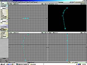
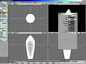
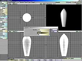
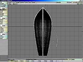
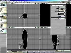
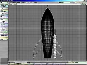
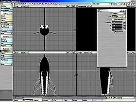
                                    P  R  E  M  I  S  E
It is already many years that I am an inveterate reader of Science Fiction  and  always I was 
enchanted from the elegant and naive Spaceships of a so-called Golden Age of Science Fiction. 
As I had to model a 3D Spaceship for a my new pic, I decided to write this tutorial, with the 
program Lightwave © Modeler,of Newteck Inc. ©.  The Spaceship is inspired by a picture of the 
great illustrator Virgil Finlay,  so this my tutorial would be also a my little homage to his 
unbounded genius.  This tutorial is good either for Pc or for MacIntosh computers. Click with 
your  mouse  on  the small pictures  near  the  words  and  you  can  see  them  more  large. 
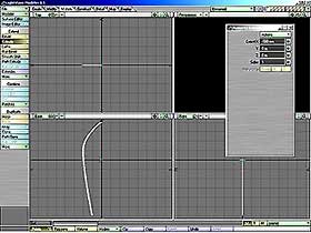
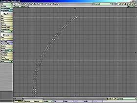
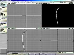
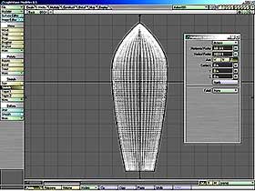
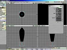
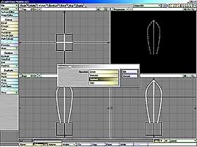
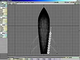
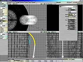
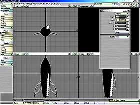
                                 P  R  O  C  E  D  U  R   E

Open Lightwave Modeler ©  and  set  the  Grid  to mt. 5. 
Click  on  Create/Bezier  and  make on the Back View the 
External Curve of the Spaceship. 
Image01
Image02

 Select the Curve  and  click on Construct/Freeze to make 
 it a poligonal object.  Click after  on Multiply/Extrude 
 and extrude it of mm.-500 on X Axis. 

Delete the Polygons with Construct/Rem Polygons  and let 
only points. Select the points in excess and delete them
Image03
Image04

 Select the single points,  sequentially,  without forget 
 anyone of them. Click after on Create/Make Pol. 

Click on  Multiply/Lathe  and  put the following values:
Sides = 45. Axis = Y.  Start Angle = 0. End Angle = 360. 
Deselect Lathe and with Detail/Surfaces (q) create a new
surface with the name of Main Starship. 
Image05
Image06

 Copy all the content of Layer 1 in Layer 2 with Copy and 
 Paste.  Click Layer 2 as Main Layer  and  after click on 
 Modify/Size with Factor at 105%. 

Select Layer 3 as Main Layer,  after click on Create/Box 
and insert the following values: 
Low X=mt.-16. Low Y=mt.-35. Low Z=mt.-15. High X=mm.-250 
High Y=mt.-23. High Z=mm.-250.  Segmentes X=1, Y=1, Z=1. 
Image07
Image08

 Click on Multiply/Mirror  and duplicate the Box first on 
 X Axis and after on Z Axis.  Now you will have  4 Boxes.

Select Layer 2 as Main Layer  and  Layer 3  as Secondary 
Layer, then click on Multiply/Boolean/Subtract. 
Image09
Image10

 Now it's necessary to enlarge a few  the Basis Spaceship 
 on Layer 1,  so that the ribs you’ve created can be well
 adherent to the Spaceship. So go on Layer 1 and click on 
 Modify/Stretch and insert the following values:
 Horizontal  Factor = 101%  and  Vertical  Factor = 103%. 

Select Layer 4 as Main Layer  and  Layer 1  as Secondary 
Layer, then click on Create/Box and insert these values: 
Low X=mt.-10. Low Y=mt.-47,5. Low Z=mt.-10. High X=mt.10 
High Y=mt.31,42. High Z=mt.10.  Segmentes X=1, Y=1, Z=1. 
This is necessary  to cut after in a right way the Ribs. 
Image11
Image12

 Select Layer 2 as Main Layer  and  Layer 4  as Secondary 
 Layer,  then click  on Multiply/Boolean/Subtract  to cut 
 right the Ribs.  After  click on  Detail/Surface (q) and 
 create  a new Surface  with  the name  of External Ribs. 

In Single  Right View  select with Right Mouse,  that is 
with Lasso, a few of points at a time  of the Rib on the 
right,  as you can see in the picture on side,  and move 
them  with Modify/Move (t), so that  you could shape, on 
the Rib,  the Main Aileron.  After,  with Cut and Paste, 
put the Ribs so modified from Layer 2 to Layer 1. 
Image13
Image14

 The Spaceship on Layer 1  seems to be too much flattened 
 so it is necessary a little correction. So, with Layer 1 
 as Main Layer,  click  on Modify/Stretch  and  insert on 
 Vertical Factor a value of 150%.  Yes, now the Spaceship 
 is really better! 

Select Layer 2 as Main Layer  and  Layer 1  as Secondary 
Layer. In Points Mode and with Create/Points (+), create 
the  points  of the outline  of the Left Aileron.  After 
select once a time,  sequentially, all the points you’ve 
created and click on Create/Make Pol (p). 
Image15
Image16

 In Polygons Mode,  click on Multiply/Extrude and extrude 
 the Left Aileron of cm. 50 on Z Axis. 

Click on  Modify/Rotate  and after rotate of -15 Degrees 
on the Y Axis the Left Aileron. 
Image17
Image18

 Click on Multiply/Mirror  and  create on X Axis also the 
 Right Aileron.  Always  with Layer 2  as Main Layer  and
 Layer 1 as Secondary Layer,  click  on Multiply/Boolean/
 Subtract  to  cut  the  joining  of the Ailerons  at the 
 Nacelle of the Spaceship. 

It is now necessary  to create  the Propulsion Reactors. 
Set the Size  of the Grid to Mt.2 and with Create/Points
create a group of points  as in the picture on side.  To 
make it more easily,  you can draw only a part of points 
and after  you can  repeat it  with Multiply/Clone.  Now 
select all the points,  once a time,  sequentially, with 
SHIFT Key down, and click on Create/Make Pol (p). 
Image19
Image20

 Click on Multiply/Lathe con Sides = 24,  Asse = Y, Start 
 Angle=0, End Angle=360,  Center X=0, Y=0, Z=0 and create 
 so the first Propulsion Reactor.

Select Layer 2 as Main Layer  and  Layer 1  as secondary 
Layer.  Click on  Detail/Surfaces (q)  and  create a new 
Surface with the name of Tubes. Click on Modify/Move (t) 
and  move  the Propulsion Reactor  on  the  side  of the 
Spaceship you see in the background. 
Image21
Image22

 Click on Modify/Rotate  and  go on top of the Propulsion 
 Reactor and rotate it of -6,5 Degrees on Z Axis, so that 
 it is aligned  with the side of the Spaceship.  Click on 
 Modify/Move (t), and move it of mt.1 to put it well near 
 the Spaceship, without nasty inclusions. 

In Polygons Mode  select  the higher ending part  of the 
Propulsion Reactor. Click on Modify/Bend  and bend it of 
60 Degrees toward the side of the Spaceship. 
Image23
Image24

 Click on Modify/Rotate  and  rotate of  -60 Degrees on Y 
 Axis the Propulsion Reactor  to put it  in a correct way 
 on the right of the Main Aleron. 

Click on Multiply/Mirror  and  replicate  the Propulsion 
Reactor on the X Axis. Select Layer 2 as Main Layer  and  
click on Cut (x), after select Layer 1 as Main Layer and 
click on Paste (v).  Now all the parts of your Spaceship 
will be on Layer 1. 
Image25
Image26

 Select Layer 2 as Main Layer  and  Layer 1  as secondary 
 Layer.  Click on Create/ Disc and create a Cylinder with 
 the measures you see in the image on side.  Click now on 
 Modify/Rotate (y)  and rotate the Cylinder of 75 Degrees 
 on Z Axis  and  of 35 Degrees  on Y Axis.  Now  click on 
 Modify/Move (t)  and  move it  to put  slightly into the 
 side of the Spaceship that you see in background. 

Click on Detail/Surface (q) and give at the Cylinder the 
Surface of Main Starship.  Click on Multiply/Mirror  and 
replicate the Cylinder on X Axis. 
Image27
Image28

 Copy the Cylinders on Layer 2 to Layer 3 with Copy/Paste
 Select now Layer 3 as the Main Layer  and Layer 1 as the 
 Secondary  Layer.   Click on  Multiply/Boolean/Subtract. 
 Keep only  the middle parts  and  delete the other parts 
 of this Boolean Operation.  Click on Detail/Surfaces (q) 
 and give at your portholes the name of Glass. Select now 
 Layer 1 as the Main Layer  and  Layer 2 as the Secondary 
 Layer. Click again on Multiply/Boolean/Subtract.  So you 
 have created the Slots of the Portholes. After Copy with 
 Copy/Paste the content of Layer 3 into Layer 1. 

Delete all the contents of the Layers,  except obviously 
the content of the Layer 1.  Now in the Layer 1  will be 
your 1920 Spaceship. If you want, you can add also other 
tubes or smaller portholes too, repeating the procedures 
you have applied until now.  But you must add  certainly 
the final Surfaces  with the Surface Editor  on the left 
of the main screen of the Modeler  and  really your 1920 
Spaceship will be operative!  Click on the image on side 
and  you will see  an example  of Final Surfaces applied 
and tuned  with the so-called  Golden Age of the Science 
Fiction on the Years 1920/1940!!
Image29


Indietro
 
Avanti

I have written this page in Italian language and after I have translated it in English language.
If you find some my translation's error, excuse me and send me an e-mail with the correct version. Thanx !!
Please Remember That Everything On This Web Site Is Copyrighted.


All rights reserved. Copyright © 2000 by Francesco Franceschi.