|
|
|
|
|
|
                                    P  R  E  M  I  S  E

A pair of stereoscopic images  differs  in their relative perspective  because the two images
represent different vantage points.  This perspective difference results in horizontal shifts
of corresponding near and far points.  The horizontal shift,  known as horizontal parallax or
disparity, is closely in relation with the width of the image.  In order to obtain an optimum
stereoscopic effect  within the limits of normal viewing,  the maximum horizontal parallax in
the viewed image must be of about  1/24  of image width.  Stereoscopic images can be obtained
with a computer with the aid of 3D programs to generate 2 images of the same object or scene,
as the result of differend visual angles. This different perspective can be genearated either
moving the camera, while his focus is fixed on the object, who remains motionless, or keeping
still the camera, while the object is rotated on the axis of its height (usually the y axis).
In this case  the rotation  of the object  must change between 3 or 6 degrees and so also the
difference of the visual degree of the camera in the precedent case.

                                 P  R  O  C  E  D  U  R   E

The stages  for the building of a stereogram using a computer are two. The First Stage is the
correct creation of the two images that will become the stereogram. This creation can be made
with a 3D Program, using renderings of 3D scenes,  or with a 2D Program,  starting from every
single image. The Second Stage is the Correct Assembling of the two images previously created
so that the stereoscopic view can be led in the observer. |
F I R S T S T A G E |
Creation of the Pair of Images with a 3D Program |
In this first stage of tutorial, in example images, it was used the software Lightwave 3D ®, Copyright © of Newtek Inc., but, really, the expressed here concepts, can be performed with many other 3D programs. Yes, I really know that in Lightwave, in the Layout Camera Control Panel, there is the "Stereoscopic Rendering" and "Eye Separationes" options, but with only these you never can truly understand as the Visive Perception Stereoscopic Mechanism works. Besides, the method written here is more accurate instead of the Camera Automatic Settings. So, let's go on! If you click with your mouse on the images of this tutorial, you can see them greater and more in detail into a new window. Warning: This javascript routine, that shows greater images, when you click with mouse on smaller images, work well with Nescape ® browser, while it could have some malfunction with Explorer ® browser, also if I've adjusted the javascript routine to it, as the Explorer ® browser does not utilize pure Java language. For this, I suggest you to use Netscape ® browser to better look and read this my tutorial. |
| |||
| |||
| |||
| |||
| |||
| |||
| |||
| |||
| |||
Creation of Pair of Images with a 2D Program |
In this other part of this tutorial, in the example images, it will be utilized the 2D software Photoshop ®, Copyright © of the Adobe Systems Inc. This section of the tutorial is for many expert users as it is possible to give only indicative instructions about the creation of the Pair of Stereographic Immages, starting from a single 2D image, that it will be subdivided at first in several parts, which will come then modified, pixel for pixel, bending them to simulate a 3D perspective, but making all this procedure only in 2D mode. Obviously every image represents a separate history, therefore its subdivision in parts, to put on various layers in Photoshop, it must made according to the discretion of who is building the stereographic image. For this we can here only suggest to make such subdivision thinking at the position in 3D space that those same parts of image would occupy in the real world, giving then a gradual inclination and the same parallactic movement to those parts that in the real would be found on the same horizontal line (Axis X) in the sense of the depth (Axis Z), considering unininfluental the vertical axis (Axis Y). What instead we will explain here is like being able to bend one of the parts of the image, only using a 2D program, in order to simulate and to generate the two 3D perspectives. Repeating then the same process for all the several parts of the image and grouping them then in the respective views, the two images will be obtained and from them it will be possible finally to generate a stereogram, as it will be finally explained in the third and last part of this my tutorial. |
| ||
Remember instead that, if these objects were put in the real world along different lines of depth, also their horizontal distance must have varied, according to the following principle: if some of the objects put on one horizontal line are laterally approached between them, in the final stereoscopic view they will seem to approach the observer, while the ones moved away between them will seem to go away from the observer. | ||
| ||
| ||
| ||
These 2 images will be then mounted correctly, as it will be explained in the successive and last part of this tutorial, in order to generate the final stereogram. Obviously all the 2D technique of the creation of the two views, starting from an one 2D image, is only enough approximate and it can sure be improved. For example, the new plugins 'Kai Power Tools ® 6', Copyright © of the MetaCreations Corporation, and more exactly the 'Kpt Goo' and the 'Kpt Projector, seem to be able in helping to improve, if adequately employed, this process of simulated creation of the two perspective 3D views, starting only from a 2D image. The more important thing is to never forget to keep on with experiments... | ||
S E C O N D S T A G E |
Correct assembly of the Pair of Images with Photoshop |
The procedure is the same, either for the two really 3D images, created with a 3D program, or for the two pseudo-3D images, created starting only from a 2D image. Therefore this part of the tutorial leaves the way in which you have generated the two images, that one of the view of the left eye and that relative one to the right eye, apart and is takes care only exclusively of the final construction of stereoscopic image, called also Auto-Stereoscopy. |
| ||
| ||
| ||
| ||
| ||
| ||
Repeat the same operation also for the other layer, the one 'Image Dx', that is move Alpha 1 Channel on Selection Button, then 'Select Inverse' (SHIFT+CTRL+I), and finally 'Edit Cut' (CTRL+X). Therefore you have obtained the two full and of the same width and height images. Select one whichever of the two layers of the images, the one SN or the one DX, and put the Alpha channel 1 on Selection Button. Choice 'Image/Crop' and press the mouse to give Ok. So you have eliminated the empty and not necessary parts from yours two images. | ||
|
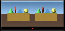
Repeat this operation with layer 'Image DX', but this time move it laterally on right, always using CTRL+V. At the end you will have the two very visible images, one on left and the other on right, with a short black space around them. So you have created your Auto-Stereogram. Remeber that, if you want see it correctly, the width of image will have to be of cm.14 approximately, because the distance between our two eyes in the real world is approximately of cm.6,5 and therefore about the same (or a multiple or a submultiple of it) it must be the distance between the centers of the two images. Therefore, if you want to print your image correctly, you must choice the menu 'Image/Image Size', deselect 'Resample Image' and insert value of cm.14 as Width. The value of Height will be adapted automatically to a new corrected value, in proportion to the new width inserted. Therefore you will be able to print a really wide cm.14 image. If, on the contrary, you want view it on screen, you must put attenction to the settings of resolution of your monitor. For a screen of 800 x 600 pixels, the final image will have to be of 350 pixels of width. A proportionally optimal dimension is of 350 x 150 pixels. But the consideration of that is optimal, obviously changes from person to person. For the stereographic images on screen, for example, the optimal dimension I like more is approximately of cm.9 of width, equivalents at an image of about 230 x 100 pixels, always for a screen resolution of 800 x 600 pixels. Therefore a good rule, when will show yours stereograms on screen is that one to introduce, on one screen, the classic version of cm.14 of width and also one proportionally more small. So you will be sure that everyone will be able to well see yours stereograms. This big tutorial ends here and I, Francesco Franceschi, the author, invite you to try it and to create yours originals stereogrammi. I hope you can have a great satisfaction creating them. Good job! |
|
|
 |
|
I have written this page in Italian language and after I have translated it in English language. If you find some my translation's error, excuse me and send me an e-mail with the correct version. Thanx !! Please Remember That Everything On This Web Site Is Copyrighted. |
)
)
)
)
)
)
)
)
)
)
)
)
)
)
)
)
)
)
)
)
)